Adiabatic capillary tube (a) block diagram (b) P-h diagram Figure
Par un écrivain mystérieux
Last updated 17 juillet 2024

Download scientific diagram | Adiabatic capillary tube (a) block diagram (b) P-h diagram Figure 1.1a shows the vapour compression system employing the adiabatic capillary tube as an expansion device. As the flow through the capillary tube is adiabatic, the enthalpy of in adiabatic capillary tube, the refrigerant expands from high pressure side to low pressure side with no heat exchange with the surroundings. The refrigerant often enters the capillary in a sub cooled liquid state [1]. As the pressure of refrigerant falls below the saturation pressure a fraction of liquid refrigerant flashes into vapor. 1.2 Diabatic Straight Capillary Tube from publication: CFD Parametric Investigation for Two Phase Flow of Refrigerant 134a In an Adiabatic Capillary tube | Capillary tubes are widely used as refrigerant flow control device in a small refrigeration systems. Since the flow behavior inside a capillary tube is complex, several physical models are necessary to predict the characteristics of refrigerant flow in the capillary tube. A | Refrigeration, Two Phase Flow and Condensation | ResearchGate, the professional network for scientists.

The figure shows a U-tube manometer containing a mercury is connected to a pipe with a fluid of 0.8 specific gravity, and this pipe has a vacuum pressure flowing through. The other
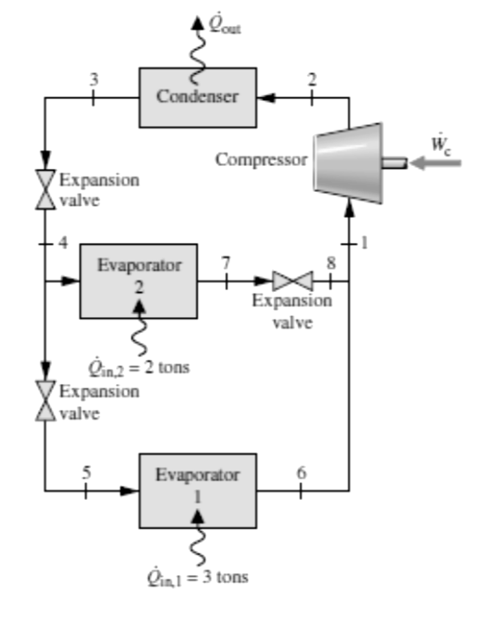
Solved The figure below shows the schematic diagram of a
Recommandé pour vous
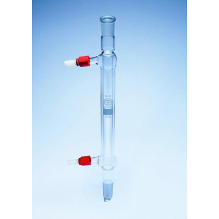 Montage verrerie Réfrigérant Air - Montage verrerie Réfrigéran14 Jul 2023
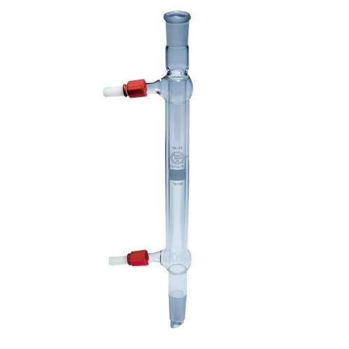 Réfrigérant droit de Liebig - Materiel pour Laboratoire14 Jul 2023
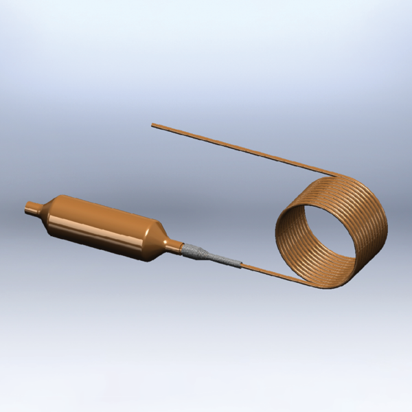 Capillary Assemblies - Strainer-Drier - Refrigeration Research14 Jul 2023
 Tube cuivre double avec écrous, pré-isolé PE - Entalpia Europe14 Jul 2023
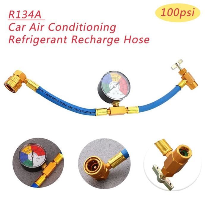 Filtres à air,R134A tuyau de Recharge réfrigérant voiture14 Jul 2023
 Diabatic capillary tube (a) block diagram (b) P-h diagram Diabatic14 Jul 2023
 Vanne perforante robinet autoperceur pour tube cuivre de frigo 3/1614 Jul 2023
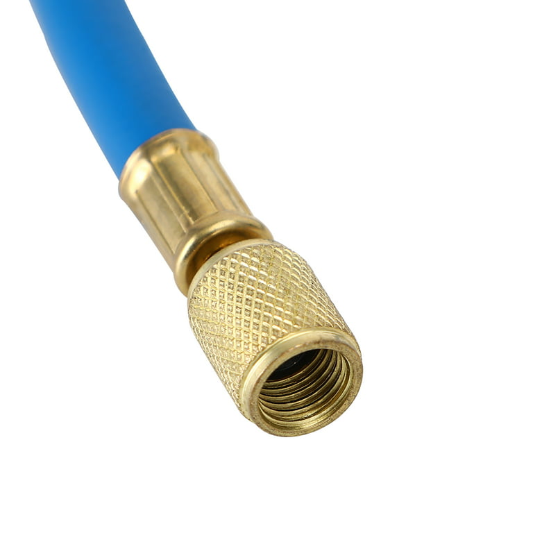 1/4 SAE 60 5' AC Charging Hoses Tube Refrigerant R134A Air14 Jul 2023
 Tuyau de charge de réfrigérant pour climatisation 60 pour R134a14 Jul 2023
 SYSTERM Conduite de réfrigérant pour climatisation split, tube en cuivre isolé prêt à l'emploi 1/4 + 1/2, les tubes préisolés pour gaz de14 Jul 2023
Tu pourrais aussi aimer
 Labyrinthe magnétique Speedy Stanley — Griffon14 Jul 2023
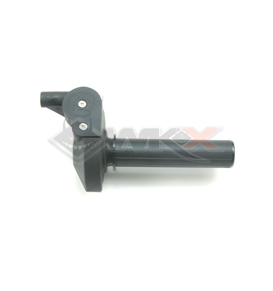 Tirage rapide réglable NOIR pour Pit Bike, Dirt Bike et Mini Moto14 Jul 2023
:quality(80)/lojaayur/catalog/coletor-menstrual-korui-leve-por-do-sol-laranja-caixa.JPG) Coletor Menstrual Korui - Leve - Pôr-do-sol - Laranja14 Jul 2023
Coletor Menstrual Korui - Leve - Pôr-do-sol - Laranja14 Jul 2023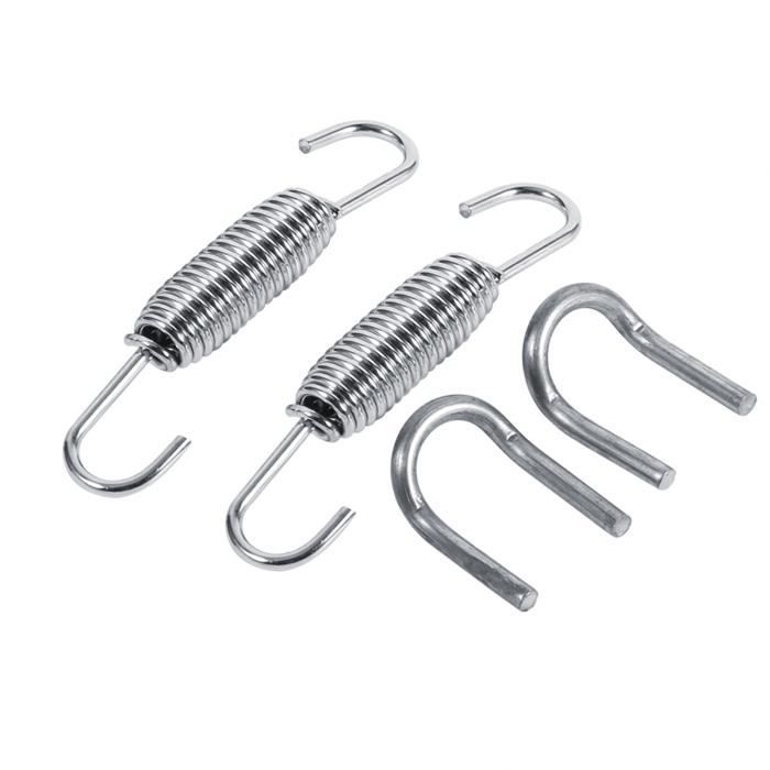 SURENHAP Ressort de tuyau d'échappement 2x système d'échappement de moto ressorts de montage entièrement rotatifs en acier auto pot - Cdiscount Auto14 Jul 2023
 Jeu de 15 clés mixtes à cliquet à tête pivotante SAE14 Jul 2023
 Pôle drapeau télescopique de haute qualité avec poignée éponge mât de dra14 Jul 2023
 Ramette papier jaune A414 Jul 2023
 Les spécificités du rideau métallique à moteur électrique - Motorisationplus le blog14 Jul 2023
 Aménager un coin lecture chez soi : inspirations14 Jul 2023
![Installez le conduit GPR ISO 80mm d'Unelvent [810123]](https://www.domomat.com/28729-large_default/o.jpg) Installez le conduit GPR ISO 80mm d'Unelvent [810123]14 Jul 2023
Installez le conduit GPR ISO 80mm d'Unelvent [810123]14 Jul 2023