Interference of EM Waves - ppt download
Par un écrivain mystérieux
Last updated 06 juillet 2024
Constructive Interference: Waves add - larger amplitude. These waves are “In Phase” Destructive Interference: Waves cancel - smaller amplitude. These waves are “Out of Phase” They are out of sync by ½λ Interference in action: Prepared by Vince Zaccone For Campus Learning Assistance Services at UCSB
Physics 6C. Interference of EM Waves. Prepared by Vince Zaccone. For Campus Learning Assistance Services at UCSB.
Waves add - larger amplitude. These waves are In Phase Destructive Interference: Waves cancel - smaller amplitude. These waves are Out of Phase They are out of sync by ½λ. Interference in action: Prepared by Vince Zaccone. For Campus Learning Assistance Services at UCSB.
2𝑡=𝑚 𝜆 0 𝑛 𝑓𝑖𝑙𝑚 ↔𝑃𝑟𝑒𝑠𝑒𝑟𝑣𝑒 𝑃ℎ𝑎𝑠𝑒. 2𝑡= 𝑚+ 1 2 𝜆 0 𝑛 𝑓𝑖𝑙𝑚 ↔𝑆ℎ𝑖𝑓𝑡 𝑃ℎ𝑎𝑠𝑒 𝑏𝑦 𝜆 2. Basic idea is that we will compare the two reflections. If they are in phase we have constructive interference (bright). If they are out of phase we have destructive interference (dark). Important details: When light reflects from a higher-index medium it is phase-shifted by ½ of a wavelength. No shift when reflecting from lower index. No shift for refracted light. The wavelength in the formulas is the wavelength in the film, so we have to divide the vacuum wavelength by the index of the film. Phase Shift Animation. Prepared by Vince Zaccone. For Campus Learning Assistance Services at UCSB.
A thin layer of magnesium fluoride (n=1.38) is used to coat a flint-glass lens (n=1.61). What thickness should the MgF2 coating be to suppress the reflection of 595nm light Prepared by Vince Zaccone. For Campus Learning Assistance Services at UCSB.
A thin layer of magnesium fluoride (n=1.38) is used to coat a flint-glass lens (n=1.61). What thickness should the MgF2 coating be to suppress the reflection of 595nm light Air n=1. MgF2 n=1.38. Glass n= Prepared by Vince Zaccone. For Campus Learning Assistance Services at UCSB.
A thin layer of magnesium fluoride (n=1.38) is used to coat a flint-glass lens (n=1.61). What thickness should the MgF2 coating be to suppress the reflection of 595nm light Air n=1. MgF2 n=1.38. Glass n= We need destructive interference (no reflection). In this case both outgoing rays reflect from a higher index, so there is no relative phase shift. Our formulas are: Prepared by Vince Zaccone. For Campus Learning Assistance Services at UCSB.
A thin layer of magnesium fluoride (n=1.38) is used to coat a flint-glass lens (n=1.61). What thickness should the MgF2 coating be to suppress the reflection of 595nm light Air n=1. MgF2 n=1.38. Glass n= We need destructive interference (no reflection). In this case both outgoing rays reflect from a higher index, so there is no relative phase shift. Our formulas are: We can use any integer m≥0, so start with m=0 and solve for t. This will give the minimum thickness. Prepared by Vince Zaccone. For Campus Learning Assistance Services at UCSB.
A thin layer of magnesium fluoride (n=1.38) is used to coat a flint-glass lens (n=1.61). What thickness should the MgF2 coating be to suppress the reflection of 595nm light Air n=1. MgF2 n=1.38. Glass n= We need destructive interference (no reflection). In this case both outgoing rays reflect from a higher index, so there is no relative phase shift. Our formulas are: To get other possible thicknesses that will work, just use larger values for m: We can use any integer m>0, so start with m=0 and solve for t. This will give the minimum thickness. Prepared by Vince Zaccone. For Campus Learning Assistance Services at UCSB.
a) What is the minimum soap-film thickness (n=1.33) in air that will produce constructive interference in reflection for red (λ=652nm) light (assume normal incidence) b) Which visible wavelength(s) will destructively interfere when reflected from a soap film of thickness 613nm Assume a range of 350nm to 750nm for visible light. Prepared by Vince Zaccone. For Campus Learning Assistance Services at UCSB.
a) What is the minimum soap-film thickness (n=1.33) in air that will produce constructive interference in reflection for red (λ=652nm) light (assume normal incidence) b) Which visible wavelength(s) will destructively interfere when reflected from a soap film of thickness 613nm Assume a range of 350nm to 750nm for visible light Air n=1. Water n=1.33. Air n=1. Prepared by Vince Zaccone. For Campus Learning Assistance Services at UCSB.
a) What is the minimum soap-film thickness (n=1.33) in air that will produce constructive interference in reflection for red (λ=652nm) light (assume normal incidence) b) Which visible wavelength(s) will destructively interfere when reflected from a soap film of thickness 613nm Assume a range of 350nm to 750nm for visible light Air n=1. Water n=1.33. Air n=1. The outgoing rays will interfere, and there is a relative phase shift, since ray 1 reflects from a higher index, but ray 2 does not. This yields the following formulas: Prepared by Vince Zaccone. For Campus Learning Assistance Services at UCSB.
a) What is the minimum soap-film thickness (n=1.33) in air that will produce constructive interference in reflection for red (λ=652nm) light (assume normal incidence) b) Which visible wavelength(s) will destructively interfere when reflected from a soap film of thickness 613nm Assume a range of 350nm to 750nm for visible light Air n=1. Water n=1.33. For part a) we use the constructive formula, with m=0 (we want the thinnest film possible) Air n=1. The outgoing rays will interfere, and there is a relative phase shift, since ray 1 reflects from a higher index, but ray 2 does not. This yields the following formulas: Prepared by Vince Zaccone. For Campus Learning Assistance Services at UCSB.
a) What is the minimum soap-film thickness (n=1.33) in air that will produce constructive interference in reflection for red (λ=652nm) light (assume normal incidence) b) Which visible wavelength(s) will destructively interfere when reflected from a soap film of thickness 613nm Assume a range of 350nm to 750nm for visible light Air n=1. Water n=1.33. For part a) we use the constructive formula, with m=0 (we want the thinnest film possible) Air n=1. The outgoing rays will interfere, and there is a relative phase shift, since ray 1 reflects from a higher index, but ray 2 does not. This yields the following formulas: For part b) we use the destructive formula, with different values of m (we want visible wavelengths) Prepared by Vince Zaccone. For Campus Learning Assistance Services at UCSB.
a) What is the minimum soap-film thickness (n=1.33) in air that will produce constructive interference in reflection for red (λ=652nm) light (assume normal incidence) b) Which visible wavelength(s) will destructively interfere when reflected from a soap film of thickness 613nm Assume a range of 350nm to 750nm for visible light Air n=1. Water n=1.33. For part a) we use the constructive formula, with m=0 (we want the thinnest film possible) Air n=1. The outgoing rays will interfere, and there is a relative phase shift, since ray 1 reflects from a higher index, but ray 2 does not. This yields the following formulas: For part b) we use the destructive formula, with different values of m (we want visible wavelengths) Other values of m give wavelengths that fall outside of the visible range. Prepared by Vince Zaccone. For Campus Learning Assistance Services at UCSB.
A thin film of oil (n=1.40) floats on water (n=1.33). When sunlight is incident vertically, the only colors that are absent from the reflected light are blue (458nm) and red (687nm). Estimate the thickness of the film. Prepared by Vince Zaccone. For Campus Learning Assistance Services at UCSB.
A thin film of oil (n=1.40) floats on water (n=1.33). When sunlight is incident vertically, the only colors that are absent from the reflected light are blue (458nm) and red (687nm). Estimate the thickness of the film Air n=1. Oil n=1.40. Water n=1.33. Prepared by Vince Zaccone. For Campus Learning Assistance Services at UCSB.
A thin film of oil (n=1.40) floats on water (n=1.33). When sunlight is incident vertically, the only colors that are absent from the reflected light are blue (458nm) and red (687nm). Estimate the thickness of the film Air n=1. Oil n=1.40. Water n=1.33. In this case ray 1 reflects from a higher index, but ray 1 reflects from a lower index, so there is a relative phase shift. Our formulas are: Prepared by Vince Zaccone. For Campus Learning Assistance Services at UCSB.
A thin film of oil (n=1.40) floats on water (n=1.33). When sunlight is incident vertically, the only colors that are absent from the reflected light are blue (458nm) and red (687nm). Estimate the thickness of the film. We will use the destructive interference formula for each given wavelength. Since they are the only visible wavelengths that are absent, we can deduce that they correspond to consecutive values for m in the formula Air n=1. Oil n=1.40. Water n=1.33. In this case ray 1 reflects from a higher index, but ray 1 reflects from a lower index, so there is a relative phase shift. Our formulas are: Prepared by Vince Zaccone. For Campus Learning Assistance Services at UCSB.
A thin film of oil (n=1.40) floats on water (n=1.33). When sunlight is incident vertically, the only colors that are absent from the reflected light are blue (458nm) and red (687nm). Estimate the thickness of the film. We will use the destructive interference formula for each given wavelength. Since they are the only visible wavelengths that are absent, we can deduce that they correspond to consecutive values for m in the formula Air n=1. Oil n=1.40. Water n=1.33. In this case ray 1 reflects from a higher index, but ray 1 reflects from a lower index, so there is a relative phase shift. Our formulas are: At this point we have some algebra to do. My preference is to find the integer value of m that fits the formulas, then plug that in to find t. Prepared by Vince Zaccone. For Campus Learning Assistance Services at UCSB.
A thin film of oil (n=1.40) floats on water (n=1.33). When sunlight is incident vertically, the only colors that are absent from the reflected light are blue (458nm) and red (687nm). Estimate the thickness of the film. We will use the destructive interference formula for each given wavelength. Since they are the only visible wavelengths that are absent, we can deduce that they correspond to consecutive values for m in the formula Air n=1. Oil n=1.40. Water n=1.33. In this case ray 1 reflects from a higher index, but ray 2 reflects from a lower index, so there is a relative phase shift. Our formulas are: At this point we have some algebra to do. My preference is to find the integer value of m that fits the formulas, then plug that in to find t. Prepared by Vince Zaccone. For Campus Learning Assistance Services at UCSB.
Monochromatic Light. In Young’s double-slit experiment light comes from the left and passes through the slits, illuminating the screen some distance R away. The light rays from the 2 slits will travel different distances to get to the screen (except in the center). Depending on the path length difference the waves will be in phase or out of phase when they arrive at the screen. If they are in phase, they combine to give constructive interference (a bright region). Out of phase means destructive interference (dark region). Some geometry gives us a formula for this difference in path length: dsin(θ). This yields the following formulas: m can be any integer (m=0,±1,±2,±3,±4,…) y = actual distance on screen (from center) Prepared by Vince Zaccone. For Campus Learning Assistance Services at UCSB.
Light with wavelength 546nm passes through two slits and forms an interference pattern on a screen 8.75m away. If the linear distance on the screen from the central fringe to the first bright fringe above it is 5.16cm, what is the separation of the slits Prepared by Vince Zaccone. For Campus Learning Assistance Services at UCSB.
Light with wavelength 546nm passes through two slits and forms an interference pattern on a screen 8.75m away. If the linear distance on the screen from the central fringe to the first bright fringe above it is 5.16cm, what is the separation of the slits This should be a straightforward problem. We are given enough information to just use our formulas. Start with the formula involving the distance on the screen: Prepared by Vince Zaccone. For Campus Learning Assistance Services at UCSB.
Light with wavelength 546nm passes through two slits and forms an interference pattern on a screen 8.75m away. If the linear distance on the screen from the central fringe to the first bright fringe above it is 5.16cm, what is the separation of the slits This should be a straightforward problem. We are given enough information to just use our formulas. Start with the formula involving the distance on the screen: Use this angle in the formula for bright fringes, with m=1. Prepared by Vince Zaccone. For Campus Learning Assistance Services at UCSB.
Light with wavelength 546nm passes through two slits and forms an interference pattern on a screen 8.75m away. If the linear distance on the screen from the central fringe to the first bright fringe above it is 5.16cm, what is the separation of the slits This should be a straightforward problem. We are given enough information to just use our formulas. Start with the formula involving the distance on the screen: Use this angle in the formula for bright fringes, with m=1. Since the angle was small we could have used the approximate formula: Prepared by Vince Zaccone. For Campus Learning Assistance Services at UCSB.
These work just like the double slit experiment (same formula), but the bright spots are narrower, and the dark spots are wider. If the grating has more slits the result is a sharper image, with narrower bright fringes. Prepared by Vince Zaccone. For Campus Learning Assistance Services at UCSB.
When light encounters an obstacle it will exhibit diffraction effects as the light bends around the object or passes through a narrow opening. Notice the alternating bright and dark bands around the edge of the razor blade. This is due to constructive and destructive interference of the light waves. Prepared by Vince Zaccone. For Campus Learning Assistance Services at UCSB.
Formulas for Destructive Interference (dark fringes) Formulas for Constructive Interference (bright fringes) These approximate formulas work when the angle is small. Similar to the double-slit experiment. The formulas are opposite (the geometry just comes out that way). Notice that the central maximum is double-width compared to the others. This is how you can tell a single-slit pattern from a multiple-slit pattern. Prepared by Vince Zaccone. For Campus Learning Assistance Services at UCSB.
How many dark fringes will be produced on either side of the central maximum if green light (λ=553nm) is incident on a slit that is 2µm wide Prepared by Vince Zaccone. For Campus Learning Assistance Services at UCSB.
How many dark fringes will be produced on either side of the central maximum if green light (λ=553nm) is incident on a slit that is 2µm wide This is a single-slit problem, so the formula for the dark fringes is: Prepared by Vince Zaccone. For Campus Learning Assistance Services at UCSB.
How many dark fringes will be produced on either side of the central maximum if green light (λ=553nm) is incident on a slit that is 2µm wide This is a single-slit problem, so the formula for the dark fringes is: Let’s find the angles to the first few dark fringes. We get a new angle for each value of m. When we try to calculate with m=4 we get a calculator error. Why doesn’t it work m. θ ° 2. 34° 3. 56° 4. Prepared by Vince Zaccone. For Campus Learning Assistance Services at UCSB.
How many dark fringes will be produced on either side of the central maximum if green light (λ=553nm) is incident on a slit that is 2µm wide This is a single-slit problem, so the formula for the dark fringes is: Let’s find the angles to the first few dark fringes. We get a new angle for each value of m. When we try to calculate with m=4 we get a calculator error. Why doesn’t it work m. θ ° 2. 34° 3. 56° 4. Recall the single-slit diffraction diagram. For the fringes to show up on the screen, the angle must be less than 90°. Of course the pattern gets very dim near the edges, but mathematically the formula will break down when sin(θ)>1. R. Prepared by Vince Zaccone. For Campus Learning Assistance Services at UCSB.
How many dark fringes will be produced on either side of the central maximum if green light (λ=553nm) is incident on a slit that is 2µm wide This is a single-slit problem, so the formula for the dark fringes is: Let’s find the angles to the first few dark fringes. We get a new angle for each value of m. When we try to calculate with m=4 we get a calculator error. Why doesn’t it work m. θ ° 2. 34° 3. 56° 4. Recall the single-slit diffraction diagram. For the fringes to show up on the screen, the angle must be less than 90°. Of course the pattern gets very dim near the edges, but mathematically the formula will break down when sin(θ)>1. R. So it looks like we will get 3 dark fringes. Prepared by Vince Zaccone. For Campus Learning Assistance Services at UCSB. 37.
Light passing through a circular opening gives a circular pattern. A formula to find the first dark fringe is: 𝑠𝑖𝑛𝜃=1.22 𝜆 𝐷. This can be taken as the angular resolution of the aperture. When two light sources are close together this angle limits our ability to resolve them as separate objects. Prepared by Vince Zaccone. For Campus Learning Assistance Services at UCSB.
Example: You are driving at night on a long straight highway in the desert as another vehicle approaches. What is the maximum distance at which you can tell that it is a car rather than a motorcycle by seeing its headlights, which are separated by a distance of 1.5m Assume your visual acuity is limited only by diffraction. Use 550 nm for the wavelength, and pupil diameter 6.0mm. What answer do you get if you use a more realistic, typical visual acuity with θmin=5x10⁻⁴ rad Prepared by Vince Zaccone. For Campus Learning Assistance Services at UCSB.
Electromagnetic Interference (EMI) - ppt video online download

Interference of Light Waves & Young's Experiment: Videos and Examples

Best Electromagnetic Interference Royalty-Free Images, Stock

1.5 interference

Free Interference, Diffraction & Polarization Of Light
PPT - Wave Optics PowerPoint Presentation, free download - ID:1137946
Wave Propagation in Lossy Dielectrics
Physics : Class 12th : Optics - PowerPoint Slides - LearnPick India

Electromagnetic Waves Classification of Electromagnetic Wave
Recommandé pour vous
 Blackview Wave 6C Smartphone 6.5'' HD Display Octa Core 5100mAh14 Jul 2023
 Blackview Mobile Phones Sim Free Unlocked, WAVE 6C Android 1314 Jul 2023
 Waves C6 Multiband Compressor14 Jul 2023
- CHM Group - Lae peeps, listen up! 📢 The 𝗕𝗹𝗮𝗰𝗸𝘃𝗶𝗲𝘄14 Jul 2023
 Blackview WAVE 6C Android 13 téléphones portables débloqués, Écran14 Jul 2023
 Top Down View Of Ocean Wave by Stocksy Contributor C6 Studio14 Jul 2023
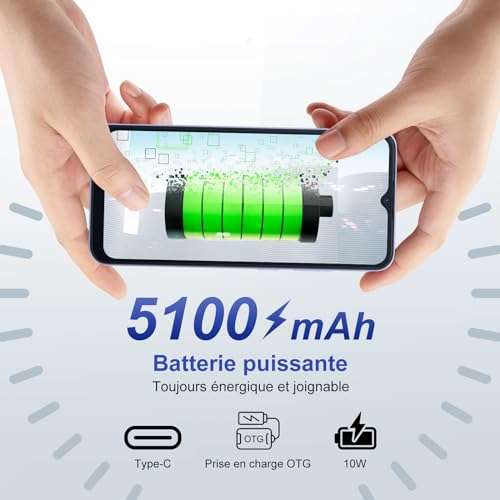 Smartphone 6.5 Blackview Wave 6C (vendeur tiers) –14 Jul 2023
) Smartphone Blackview WAVE 6C Android smartPhone Noir - 6.52 dual14 Jul 2023
Smartphone Blackview WAVE 6C Android smartPhone Noir - 6.52 dual14 Jul 2023 Reinders 206116R-B C6 LED Light Strands - Champagne Full Wave14 Jul 2023
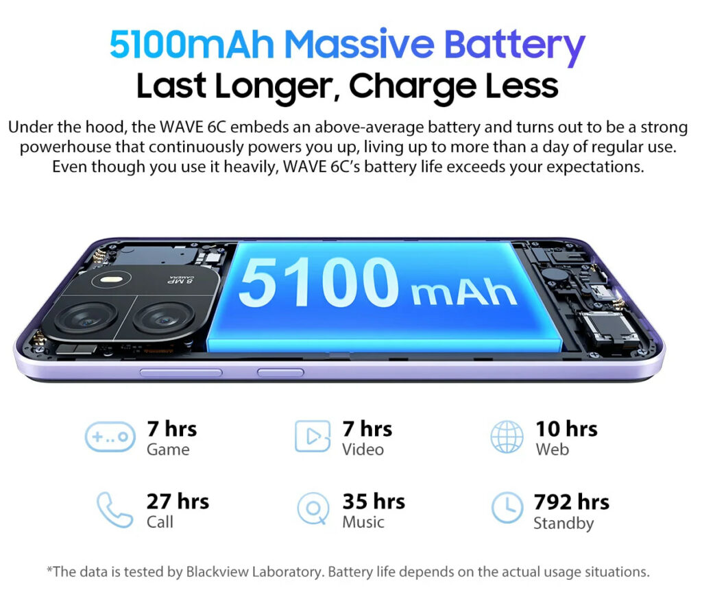 Blackview Wave 6C - Shpresa AL Computers14 Jul 2023

Tu pourrais aussi aimer
 Tuyau pour aspirateur d'atelier Dewalt 2 1/2 po x 7 pi - Canac14 Jul 2023
 Bague Al tize - Bijoux uniques argent/ Adeline Beaujoin, créateur14 Jul 2023
 FREESTYLE LIBRE 2 SENSOR14 Jul 2023
 Appareil Photo Instantané KODAK PRINTOMATIC - 10.0 MP - Compact avec imprimante photo - Vert d'eau - Cdiscount Appareil Photo14 Jul 2023
 Nidal-1 Milk Pdr 700G14 Jul 2023
 Pro-Max PGT14E 14″ Two-Sided Panini Grill – Grooved Aluminum Platens – Electronic Temp Control and Timer – 120V - Star Manufacturing14 Jul 2023
 ÉQUIPEMENTS ET OUTILS DE GARAGE14 Jul 2023
 Vente en ligne d'armes de tir sportif - Armurerie Centrale14 Jul 2023
 VEGCOO 25 Pièces Barrette Cheveux Femme, Barrette Cheveux Femme pour Bébé Fille, Barettes Cheveux Fille, Barrette Bebe Anti Glisse (Multicolore) : : Beauté et Parfum14 Jul 2023
 Le nouveau collier à mâcher sensoriel réduit la mastication de l’agitation pour les enfants adultes14 Jul 2023